Mastering the Perfect Connection: Wiring, Configuring, and Debouncing Switches in ESPHome
Disclosure: This post contains affiliate links. If you click through and make a purchase, I will earn a commission, at no additional cost to you. Read my full disclosure here.
The satisfying click of a button or the flick of a switch may seem like simple actions, but behind the scenes, they're a gateway to a myriad of opportunities within the realm of ESPHome. By connecting a humble switch or button to your ESP8266 or ESP32, you're given the power to orchestrate a symphony of smart devices – from LEDs and relays to motors – all through your ESPHome node. The magic doesn't stop there; you can even relay the button status to Home Assistant, enabling centralized control of every integrated device. Imagine turning your home into a well-conducted orchestra, with a single button managing all the connected light bulbs in your smart abode.
The magic doesn't stop with components hooked up to the ESPHome node itself; you can even relay the button status to Home Assistant, enabling centralized control of every integrated device. Imagine turning your home into a well-conducted orchestra, with a single button managing all the connected light bulbs in your smart abode.
Mastering the art of configuring physical switches and buttons in ESPHome is essential for anyone dabbling in project planning. Allow me to guide you through the process, ensuring even ESPHome newcomers can effortlessly wire up a switch or button and configure it using YAML. With this comprehensive understanding, you'll be ready to embark on your first project, making the right connections from the get-go.
A world of variety at your fingertips
Switches come in a delightful assortment of shapes and types, each with their unique characteristics, ready to fulfil your project's needs. Among these, you'll find tactile or momentary switches – the quintessential push buttons that spring into action when pressed, only to return to their original state once released, thus interrupting the circuit.
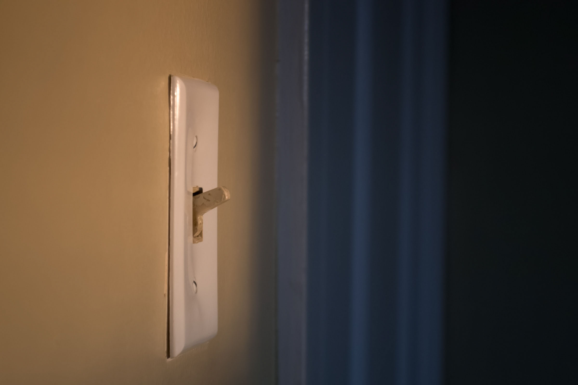
In contrast, toggle switches stand their ground, steadfast in their on or off positions. With the flip of a lever, you can open or close the electrical circuit, giving you control with a satisfying sense of permanence.
For example, if you turn the software switch on, but the physical switch is off, you would have to first turn the physical switch off, then on, to turn the device on again. This can lead to confusion and frustration. Therefore, I would not recommend using toggle switches in ESPHome projects, even though they can be fun to play with.
The toggle switch conundrum: Not all that glitters is gold
Toggle switches, with their satisfying clicks and steadfast positions, certainly have a charm of their own. However, when it comes to integrating them with ESPHome and Home Assistant, their lustre begins to fade. If a toggle switch serves as the sole controller for a component connected to the node, all is well in the world of ESPHome. However, once you introduce Home Assistant's dashboard into the equation, synchronization issues may arise. Imagine a scenario where you activate the software switch, yet the physical toggle remains off. To turn the device on again, you must first flip the physical switch off and then on, a process that can cause confusion and frustration.
While toggle switches possess an undeniable appeal, their limitations within ESPHome projects are evident. As a conscientious guide, I must advise against their use in such endeavours, despite the undeniable joy of playing with them.
The art of connection: Wiring a switch to an ESP8266 or ESP32
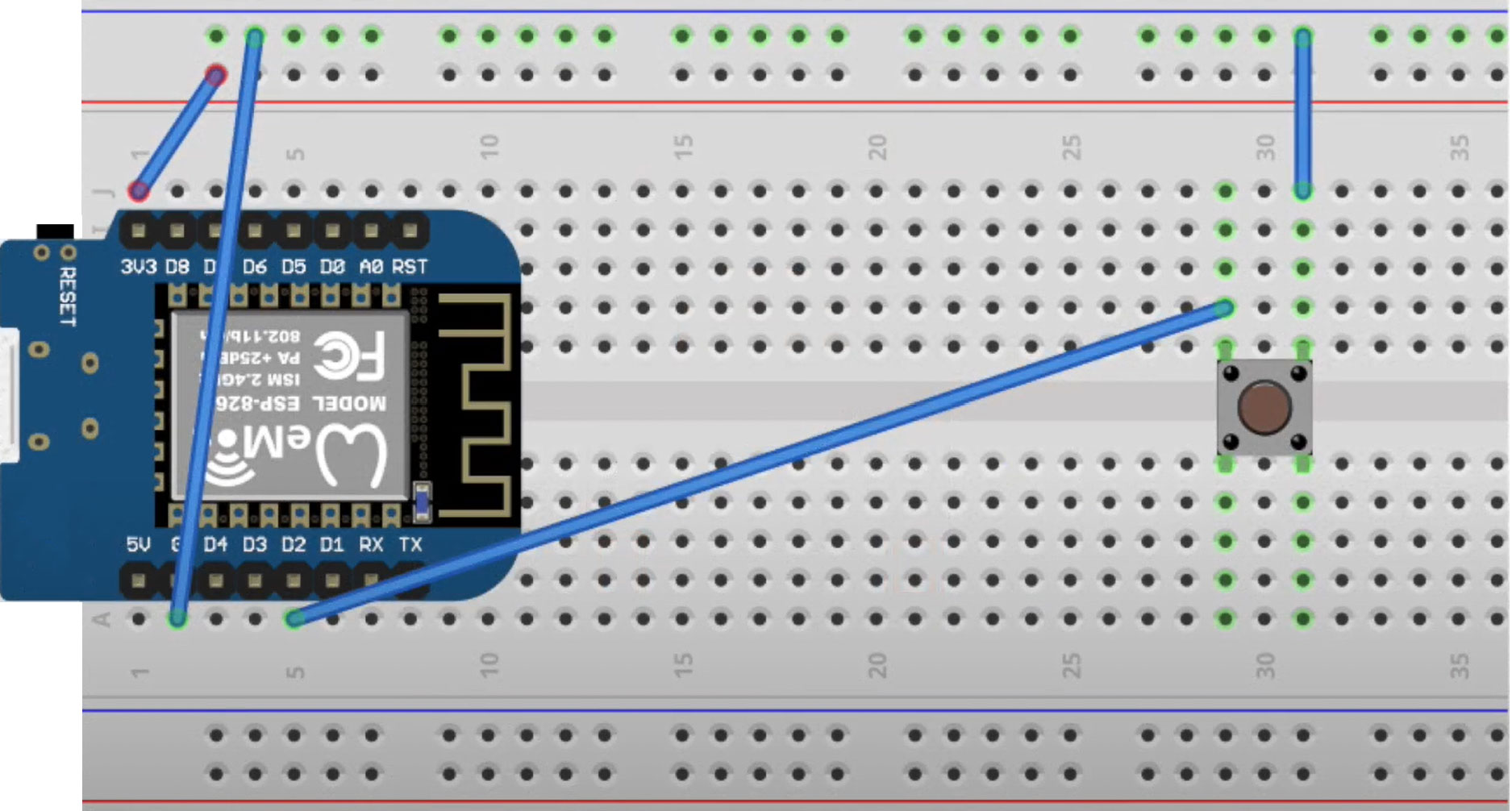
Wiring a switch to your ESP8266 or ESP32 board is a breeze. Simply create a connection between one terminal of the switch and the ground on the board (marked with a “G”). Then, link the other terminal to a GPIO pin. The end goal is for the pin to read LOW when the switch is pressed and HIGH when released.
With the button wired to your board, you can proceed to create a GPIO binary sensor in your configuration using the code provided in the documentation. In this example, the device class is set to “window”, but you can select from any of the device classes supported by Home Assistant.
Once the button is wired, we can create a GPIO binary sensor in our configuration using the code provided in the documentation. In this example, the device class is set to “window”. You can choose from any of the device classes supported by Home Assistant.
GPIO, or General Purpose Input/Output, refers to digital pins found in microcontrollers, such as the ESP8266 or ESP32. These pins are the versatile workhorses of the microcontroller world, capable of performing both input and output operations.
Think of GPIO pins as the communicative link between your microcontroller and various external devices, such as sensors, actuators, or switches. They can read data from these devices, interpret their signals, or send data to control their behaviour – a true testament to their adaptability.
The secret ingredient: Configuring the ESP8266's or ESP32's internal pull-up resistor in ESPHome
In our current setup, pressing the momentary button causes the pin to read LOW. However, releasing the switch doesn't guarantee that the pin will read HIGH. This uncertainty is due to a phenomenon known as a “floating pin”. A floating pin, sometimes referred to as a “floating input,” is a digital input pin that isn't connected to either a HIGH (VCC) or LOW (Ground) voltage level. In this state of limbo, the pin's voltage level fluctuates unpredictably due to electrical noise, making it difficult to determine whether it's reading HIGH or LOW. The floating pin issue arises when a momentary button is released, and the input pin isn't actively connected to a known voltage level. This lack of a definite connection leads to the pin's uncertain state, causing unreliable readings and potential miscommunication between the switch and the microcontroller.
To vanquish this floating pin issue, we have two options at our disposal. One is to employ a physical pull-up resistor, which ensures a known state for the signal. The other, more convenient solution, involves enabling the built-in pull-up resistor on the ESP8266 or ESP32 boards within the ESPHome configuration. The key to unlocking the internal pull-up resistor lies in a few lines of YAML code, effortlessly integrated into your ESPHome configuration. This simple addition keeps the pin in a known state, ensuring reliable communication between your switch and the microcontroller.
In our current configuration, ESPHome interprets the switch as off when pressed and on when not pressed. However, should you prefer to reverse this behaviour, a simple tweak to your code is all it takes. To invert the switch's status in ESPHome, simply add the following line to your YAML configuration:
With this adjustment, ESPHome will now report the switch as on when pressed and off when not pressed, catering to your desired setup.
A smoother transition: Debouncing in ESPHome
When releasing a momentary switch like the one used in our example, the transition from LOW to HIGH isn't as instantaneous as one might expect. Instead, the switch briefly oscillates before reaching its final state. This rapid, short-lived fluctuation can lead to ESPHome reading incorrect values, creating the illusion of rapid switching between states.
To overcome this hiccup, we turn to a process known as debouncing. Debouncing in electronics helps filter out the transient oscillations, ensuring that ESPHome reads stable and accurate values. Thankfully, implementing debouncing in ESPHome requires just a few lines of code. To apply debouncing to your ESPHome configuration, refer to the official documentation on debouncing values and follow the provided instructions. With this simple addition, your switch will enjoy a smoother, more reliable transition between states, free from the interference of unwanted oscillations.
By implementing a debounce filter in your ESPHome configuration, you establish a threshold to ensure the signal's stability. The filter only registers the signal as high if the button remains high for more than 10 ms. This time constraint effectively filters out the transient oscillations, providing a clear and stable signal. This refined filter ensures that any minor fluctuations are eliminated, leaving behind a reliable signal for ESPHome to interpret. With the debounce filter in place, your setup benefits from improved accuracy and smoother transitions between states, allowing you to focus on harnessing the power of your smart devices with confidence.
Frequently asked questions
GPIO stands for General Purpose Input/Output, which are digital pins in a microcontroller (such as the ESP8266 or ESP32) that can be used for both input and output operations. These pins can be used to interact with external devices, such as sensors, actuators, or switches, by either reading data from them or sending data to them.
The purpose of wiring a switch or button to an ESP8266 or ESP32 is to have the power to control various devices linked to your ESPHome node and to pass on the switch to Home Assistant.
Toggle switches can cause confusion and frustration because if the software switch is on, but the physical switch is off, you have to first turn off and then turn on the physical switch to turn the device on again. This can lead to the software switch and physical switch being out of sync.
A tactile or momentary switch is a push button that only functions when pressed, and the circuit is interrupted when released. On the other hand, a toggle switch remains in a fixed position either on or off and can be flipped by moving a lever to open or close the electrical circuit.
About Liam Alexander Colman
Liam Alexander Colmanis an experienced Home Assistant user who has been utilizing the platform for a variety of projects over an extended period. His journey began with a Raspberry Pi, which quickly grew to three Raspberry Pis and eventually a full-fledged server. Liam's current operating system of choice is Unraid, with Home Assistant comfortably running in a Docker container. With a deep understanding of the intricacies of Home Assistant, Liam has an impressive setup, consisting of various Zigbee devices, and seamless integrations with existing products such as his Android TV box. For those interested in learning more about Liam's experience with Home Assistant, he shares his insights on how he first started using the platform and his subsequent journey.
Comments
Thanks for your tutorial. However i’ve tried it and nothing happens when I press the button. What is meant to happen in Home Assistant?


Thanks for your tutorial. However i’ve tried it and nothing happens when I press the button. What is meant to happen in Home Assistant?